|
I- Analyse de la documentation constructeur |
I - Analyse de la documentation constructeur
 La fiche technique du composant (datasheet) : https://datasheets.maximintegrated.com/en/ds/DS1621.pdf
I-1 Description du composant
DESCRIPTION
The DS1621 Digital Thermometer and Thermostat provides 9-bit temperature readings, which indicate the temperature of the device. The thermal alarm output, TOUT, is active when the temperature of the device exceeds a user-defined temperature TH. The output remains active until the temperature drops below user defined temperature TL, allowing for any hysteresis necessary. User-defined temperature settings are stored in nonvolatile memory so parts may be programmed prior to insertion in a system. Temperature settings and temperature readings are all communicated to/from the DS1621 over a simple 2-wire serial interface.
Traduction
……..…..….…..…..…..…..…..….…..…..…..….…..…..…..…..….……..….…..…..…..….…..…..…..…..…..….…..……..….…..…..…..….…..…..….…..…..…
……..…..….…..…..…..…..…..….…..…..…..….…..…..…..…..….……..….…..…..…..….…..…..…..…..…..….…..……..….…..…..…..….…..…..….…..…..…
……..…..….…..…..…..…..…..….…..…..…..….…..…..…..…..….……..….…..…..…..….…..…..…..…..…..….…..……..….…..…..…..….…..…..….…..…..…
……..…..….…..…..…..…..…..….…..…..…..….…..…..…..…..….……..….…..…..…..….…..…..…..…..…..….…..……..….…..…..…..….…..…..….…..…..…
……..…..….…..…..…..…..…..….…..…..…..….…..…..…..…..….……..….…..…..…..….…..…..…..…..…..….…..……..….…..…..…..….…..…..….…..…..…
……..…..….…..…..…..…..…..….…..…..…..….…..…..…..…..….……..….…..…..…..….…..…..…..…..…..….…..……..….…..…..…..….…..…..….…..…..…
I-2 Caractéristiques du composant
FEATURES
• Temperature measurements require no external components
• Measures temperatures from -55°C to +125°C in 0.5°C increments. Fahrenheit equivalent is -67°F to 257°F in 0.9°F increments
• Temperature is read as a 9-bit value (2-byte transfer) Wide power supply range (2.7V to 5.5V)
• Converts temperature to digital word in less than 1 second
• Thermostatic settings are user definable and nonvolatile
• Data is read from/written via a 2-wire serial interface (open drain I/O lines)
• Applications include thermostatic controls, industrial systems, consumer products, thermometers, or any thermal sensitive system
• 8-pin DIP or SO package (150mil and 208mil) PIN ASS
Quelle est la plage de température mesurable ?
……..…..….…..…..…..…..…..….…..…..…..….…..…..…..…..….……..….…..…..…..….…..…..…..…..…..….…..……..….…..…..…..….…..…..….…..…..…
……..…..….…..…..…..…..…..….…..…..…..….…..…..…..…..….……..….…..…..…..….…..…..…..…..…..….…..……..….…..…..…..….…..…..….…..…..…
Quelle est la résolution de ce capteur ?
……..…..….…..…..…..…..…..….…..…..…..….…..…..…..…..….……..….…..…..…..….…..…..…..…..…..….…..……..….…..…..…..….…..…..….…..…..…
……..…..….…..…..…..…..…..….…..…..…..….…..…..…..…..….……..….…..…..…..….…..…..…..…..…..….…..……..….…..…..…..….…..…..….…..…..…
Combien de bits sont nécessaires pour coder la valeur de la température mesurée ?
……..…..….…..…..…..…..…..….…..…..…..….…..…..…..…..….……..….…..…..…..….…..…..…..…..…..….…..……..….…..…..…..….…..…..….…..…..…
……..…..….…..…..…..…..…..….…..…..…..….…..…..…..…..….……..….…..…..…..….…..…..…..…..…..….…..……..….…..…..…..….…..…..….…..…..…
Combien de mots de huit bits (octet) sont nécessaires pour coder la valeur de la température ?
……..…..….…..…..…..…..…..….…..…..…..….…..…..…..…..….……..….…..…..…..….…..…..…..…..…..….…..……..….…..…..…..….…..…..….…..…..…
……..…..….…..…..…..…..…..….…..…..…..….…..…..…..…..….……..….…..…..…..….…..…..…..…..…..….…..……..….…..…..…..….…..…..….…..…..…
Nommer les deux lignes utilisées pour la transmission des données, quel est leur particularité ?
……..…..….…..…..…..…..…..….…..…..…..….…..…..…..…..….……..….…..…..…..….…..…..…..…..…..….…..……..….…..…..…..….…..…..….…..…..…
……..…..….…..…..…..…..…..….…..…..…..….…..…..…..…..….……..….…..…..…..….…..…..…..…..…..….…..……..….…..…..…..….…..…..….…..…..…
I-3 Description des broches du composant
PIN DESCRIPTION
|
SDA SCL TOUT GND |
- 2-Wire Serial Data Input/Output - 2-Wire Serial Clock - Thermostat Output Signal - Ground |
VDD A0 A1 A2 |
- Power Supply Voltage - Chip Address Input - Chip Address Input - Chip Address Input |
Compléter le tableau ci-dessous
|
N° Broche |
Nom |
Description |
|
1 |
SDA |
|
|
|
SCL |
|
|
|
TOUT |
|
|
|
GND |
|
|
|
A2 |
|
|
|
A1 |
|
|
|
A0 |
|
|
|
VDD |
|
I-4 Adressage du composant
SLAVE ADDRESS
A control byte is the first byte received following the START condition from the master device. The control byte consists of a 4-bit control code; for the DS1621, this is set as 1001 binary for read and write operations. The next 3 bits of the control byte are the device select bits (A2, A1, A0). They are used by the master device to select which of eight devices are to be accessed. These bits are in effect the 3 least significant bits of the slave address. The last bit of the control byte (R/ W ) defines the operation to be performed. When set to a “1” a read operation is selected, when set to a “0” a write operation is selected. Following the START condition the DS1621 monitors the SDA bus checking the device type identifier being transmitted. Upon receiving the 1001 code and appropriate device select bits, the slave device outputs an acknowledge signal on the SDA line.
Donner la partie fixe de l'adresse d'un DS1621 sur bus I2C ?
……..…..….…..…..…..…..…..….…..…..…..….…..…..…..…..….……..….…..…..…..….…..…..…..…..…..….…..……..….…..…..…..….…..…..….…..…..…
……..…..….…..…..…..…..…..….…..…..…..….…..…..…..…..….……..….…..…..…..….…..…..…..…..…..….…..……..….…..…..…..….…..…..….…..…..…
Combien peut-on mettre de DS1621 sur un même bus I2C ?
……..…..….…..…..…..…..…..….…..…..…..….…..…..…..…..….……..….…..…..…..….…..…..…..…..…..….…..……..….…..…..…..….…..…..….…..…..…
……..…..….…..…..…..…..…..….…..…..…..….…..…..…..…..….……..….…..…..…..….…..…..…..…..…..….…..……..….…..…..…..….…..…..….…..…..…
Compléter le tableau
|
Composant n° |
Partie fixe de l’adresse |
A2 |
A1 |
A0 |
R/W |
Adresse 8bits en hexadécimal |
||||
|
1 |
|
|
|
|
0 |
0 |
0 |
0 |
E |
|
|
|
|
|
|
0 |
0 |
0 |
1 |
L |
|
|
|
2 |
|
|
|
|
|
|
|
0 |
E |
|
|
|
|
|
|
|
|
|
1 |
L |
|
|
|
3 |
|
|
|
|
|
|
|
0 |
E |
|
|
|
|
|
|
|
|
|
1 |
L |
|
|
|
4 |
|
|
|
|
|
|
|
0 |
E |
|
|
|
|
|
|
|
|
|
1 |
L |
|
|
|
5 |
|
|
|
|
|
|
|
0 |
E |
|
|
|
|
|
|
|
|
|
1 |
L |
|
|
|
6 |
|
|
|
|
|
|
|
0 |
E |
|
|
|
|
|
|
|
|
|
1 |
L |
|
|
|
7 |
|
|
|
|
|
|
|
0 |
E |
|
|
|
|
|
|
|
|
|
1 |
L |
|
|
|
8 |
1 |
0 |
0 |
1 |
1 |
1 |
1 |
0 |
E |
|
|
1 |
0 |
0 |
1 |
1 |
1 |
1 |
1 |
L |
0x9F |
|
* E : adresse en Écriture L : adresse en Lecture
I-5 Opération et contrôle
Donner le rôle du registre de contrôle
……..…..….…..…..…..…..…..….…..…..…..….…..…..…..…..….……..….…..…..…..….…..…..…..…..…..….…..……..….…..…..…..….…..…..….…..…..…
……..…..….…..…..…..…..…..….…..…..…..….…..…..…..…..….……..….…..…..…..….…..…..…..…..…..….…..……..….…..…..…..….…..…..….…..…..…
……..…..….…..…..…..…..…..….…..…..…..….…..…..…..…..….……..….…..…..…..….…..…..…..…..…..….…..……..….…..…..…..….…..…..….…..…..…
……..…..….…..…..…..…..…..….…..…..…..….…..…..…..…..….……..….…..…..…..….…..…..…..…..…..….…..……..….…..…..…..….…..…..….…..…..…
Indiquer la configuration du registre de contrôle
|
bit 7 |
bit 6 |
bit 5 |
bit 4 |
bit 3 |
bit 2 |
bit 1 |
bit 0 |
|
. . . . |
. . . . |
. . . . |
. . . . |
1* |
0 * |
. . . . |
. . . . |
|
Msb |
* ⇒ réservé |
Lsb |
|||||
avec
DONE ⇒ ….…..…..…..….…..…..….…..…..….…..…..…..….…..…..…..….…………..…..…...........................................................….…..…..…..…..….….
……..…..….…..…..…..…..…..….…..…..…..….…..…..…..…..….……..….…..…..…..….…..…..…..…..…..….…..……..….…..…..…..….…..…..….…..…..…
……..…..….…..…..…..…..…..….…..…..…..….…..…..…..…..….……..….…..…..…..….…..…..…..…..…..….…..……..….…..…..…..….…..…..….…..…..…
THF ⇒ ….…..…..…..….…..…..….…..…..….…..…..…..….…..…..…..….…..…..…..….…..…..…..…..….…..…..….……..…..….…..…..…..…..…..….…..…..
……..…..….…..…..…..…..…..….…..…..…..….…..…..…..…..….……..….…..…..…..….…..…..…..…..…..….…..……..….…..…..…..….…..…..….…..…..…
……..…..….…..…..…..…..…..….…..…..…..….…..…..…..…..….……..….…..…..…..….…..…..…..…..…..….…..……..….…..…..…..….…..…..….…..…..…
TLF ⇒ ….…..…..…..….…..…..….…..…..….…..…..…..….…..…..…..….…..…..…..….…..…..…..…..….…..…..….……..…..….…..…..…..…..…..….…..…..
……..…..….…..…..…..…..…..….…..…..…..….…..…..…..…..….……..….…..…..…..….…..…..…..…..…..….…..……..….…..…..…..….…..…..….…..…..…
……..…..….…..…..…..…..…..….…..…..…..….…..…..…..…..….……..….…..…..…..….…..…..…..…..…..….…..……..….…..…..…..….…..…..….…..…..…
NVB ⇒ ….…..…..…..….…..…..….…..…..….…..…..…..….…..…..…..….…..…..…..….…..…..…..…..….…..…..….……..…..….…..…..…..…..…..….…..…..
……..…..….…..…..…..…..…..….…..…..…..….…..…..…..…..….……..….…..…..…..….…..…..…..…..…..….…..……..….…..…..…..….…..…..….…..…..…
……..…..….…..…..…..…..…..….…..…..…..….…..…..…..…..….……..….…..…..…..….…..…..…..…..…..….…..……..….…..…..…..….…..…..….…..…..…
POL ⇒ ….…..…..…..….…..…..….…..…..….…..…..…..….…..…..…..….…..…..…..….…..…..…..…..….…..…..….……..…..….…..…..…..…..…..….…..…..
……..…..….…..…..…..…..…..….…..…..…..….…..…..…..…..….……..….…..…..…..….…..…..…..…..…..….…..……..….…..…..…..….…..…..….…..…..…
……..…..….…..…..…..…..…..….…..…..…..….…..…..…..…..….……..….…..…..…..….…..…..…..…..…..….…..……..….…..…..…..….…..…..….…..…..…
1SHOT ⇒ ….…..…..…..….…..…..….…..…..….…..…..…..….…..…..…..….…..…..…..….…..…..…..…..….…..…..….……..…..….…..…..…..…..…..….…..
……..…..….…..…..…..…..…..….…..…..…..….…..…..…..…..….……..….…..…..…..….…..…..…..…..…..….…..……..….…..…..…..….…..…..….…..…..…
……..…..….…..…..…..…..…..….…..…..…..….…..…..…..…..….……..….…..…..…..….…..…..…..…..…..….…..……..….…..…..…..….…..…..….…..…..…
* ⇒ réservé
I-6 Commandes configuration du DS1621
|
Instruction |
Description |
Code |
Suivi de … |
* |
|
|
|
0xAA |
|
|
|
|
|
0xA8 |
|
|
|
|
|
0xA9 |
|
|
|
|
|
0xEE |
|
1 |
|
|
|
0x22 |
|
1 |
|
|
|
0xA1 |
|
2 |
|
|
|
0xA2 |
|
2 |
|
|
|
0xAC |
|
2 |
* 1 -->
* 2 -->
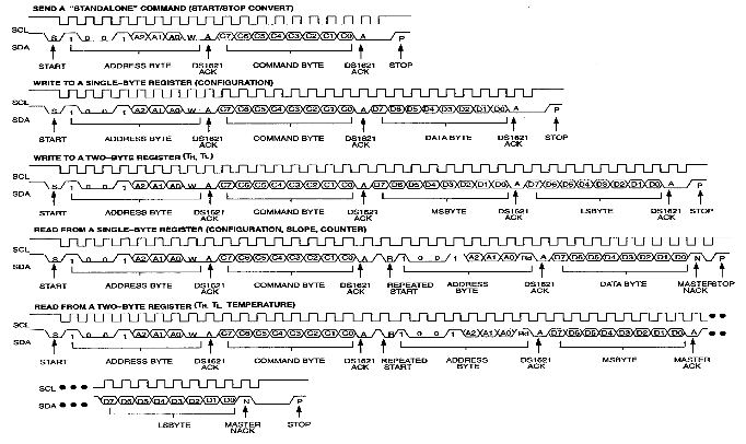
I-7 Chronogrammes de communication I2C avec un DS1621
Créé avec HelpNDoc Personal Edition: Faites de la création de fichiers d'aide CHM un jeu d'enfant avec HelpNDoc