|
6.10.a UART (RS232) |
La liaison série asynchrone, UART (pour Universal Asynchronous Receiver Transmitter) est un émetteur-récepteur asynchrone universel. Il a aussi été parfois désigné sous le nom de ACIA, pour Asynchronous Communication Interface Adapter.
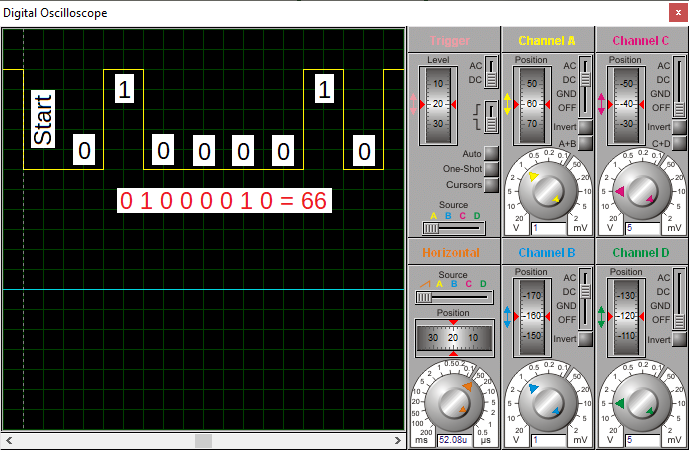
Constitution d'une trame UART
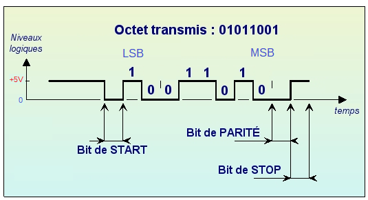
Une trame UART est constituée des bits suivants :
- Un bit de Start toujours à 0 : servant à la synchronisation du récepteur
- Données : la taille des données est comprise entre 5 et 9 bits. Bits envoyés du LSB (bit de poids faible) au MSB (bit de poids fort).
- Parité : Paire ou Impaire (optionnel)
- Fin : Un bit de Stop, toujours à 1. La durée de celui-ci varie entre 1, 1.5 et 2 (à l'utilisateur de choisir).
Vitesse de transmission
Afin de faciliter l'interopérabilité entre périphériques (PC, microcontrôleur, modem…) des vitesses de transmission sont normalisées par multiples et sous-multiples de 9600 baud, l'unité baud correspondant à un symbole par seconde :
- 110 baud
- 220 baud
- 300 baud
- 1200 baud
- 2400 baud
- 4800 baud
- 9600 baud
- 19200 baud
- 38400 baud
- 57600 baud
- 115200 baud
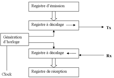
Diagramme UART
RS232 est une norme standardisant une voie de communication de type série. Disponible sur presque tous les PC depuis 1981 jusqu'au milieu des années 2000, il est communément appelé le « port série ».
Sur les systèmes d'exploitation MS-DOS et Windows, les ports RS-232 sont désignés par les noms COM1, COM2, etc.
Cela leur a valu le surnom de « ports COM », encore utilisé de nos jours. Il est graduellement remplacé par le port USB depuis l'apparition de ce dernier, et le port RS-232 n'est désormais plus employé que dans des applications professionnelles. Les liaisons RS-232 sont fréquemment utilisées dans l'industrie pour connecter différents appareils électroniques (automate, appareil de mesure, etc.).
En cas d'absence de port RS 232, il existe des adaptateurs USB/port série.
Simulation sous Proteus
Téléchargement du schéma structurel sous Proteus 8: RS232_ex01.pdsprj
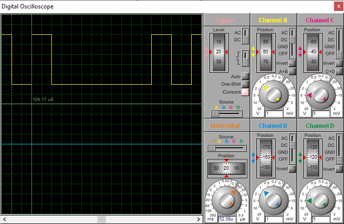
Exemple: transmission du caractère "A"
|
|
|
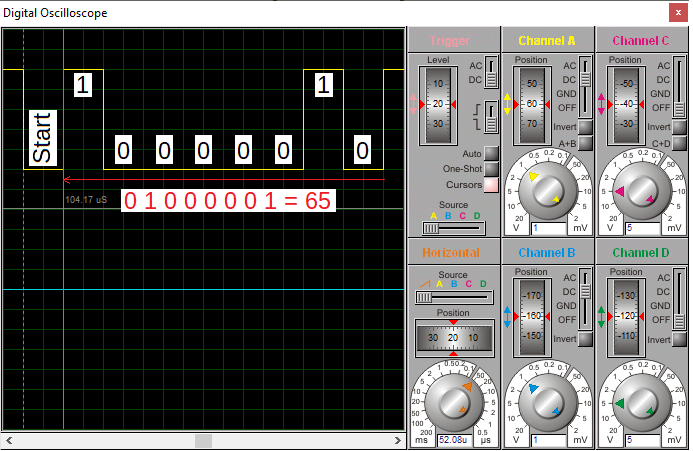
Exemple: transmission du caractère "B"
|
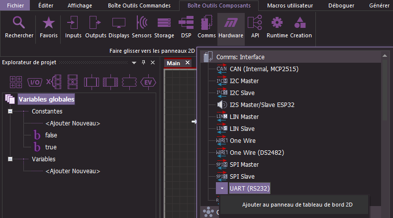
Sous Flowcode |
Sous Flowcode pour gérer la liaison série asynchrone (RS232), il faut ajouter au "Panneau tableau de bord" un composant de type "UART (RS232)"
|
Low level routines for controlling or interacting with a standard asynchronous serial interface. On a microcontroller the interface will be the onboard UART which will need voltage level shifting using a max2323 to become RS232 compatible.See the EB015 RS232 E-block for details. |
|
Routines de bas niveau pour contrôler ou interagir avec une interface série asynchrone standard. Sur un microcontrôleur, l'interface sera l'UART embarqué qui nécessitera un décalage de niveau de tension à l'aide d'un max2323 pour être compatible RS232. Voir le bloc électronique EB015 RS232 pour plus de détails. |
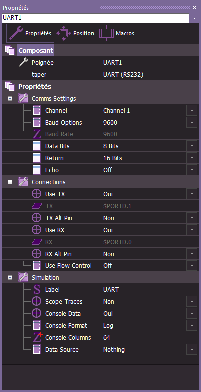
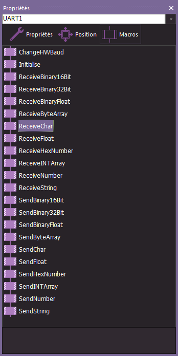
Aide du Composant: UART (RS232)
|
|
|
||||||||||||||||||||||||||||||||||||||||
|
|
|
||||||||||||||||||||||||||||||||||||||||

Exemple 1: Flowcode_328P_RS232_Exemple1.fcfx
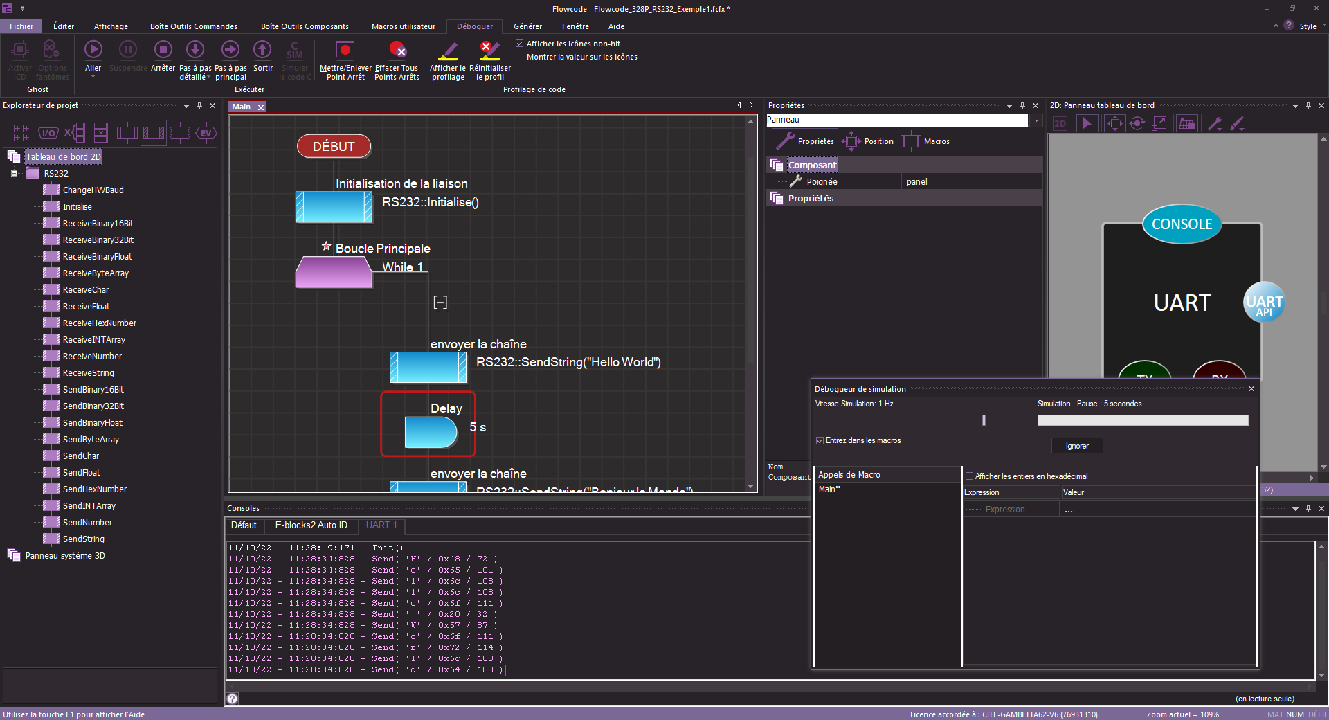
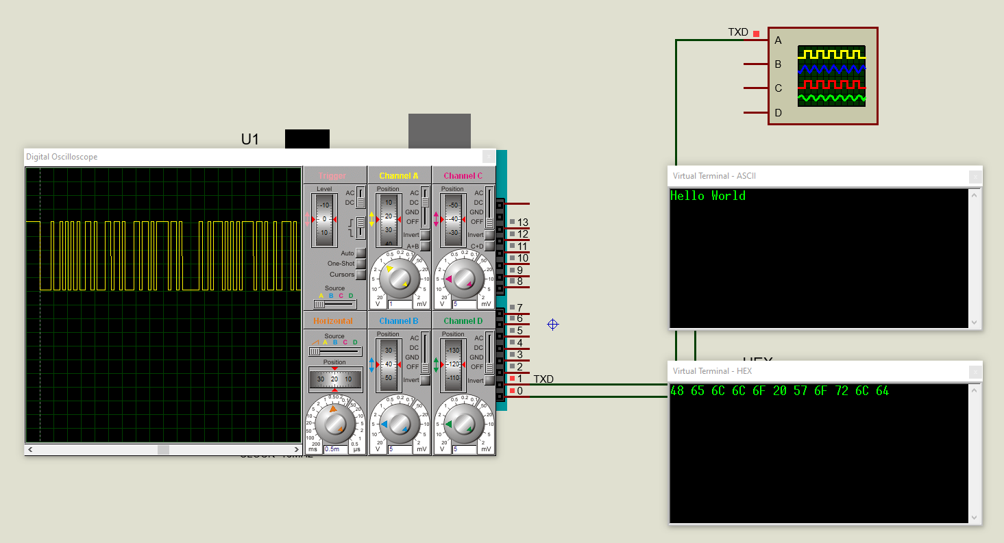
Simulation sous proteus (Flowcode_328P_RS232_Exemple1.rar)
|
Sous Arduino |
Fonction Serial
Description
Used for communication between the Arduino board and a computer or other devices. All Arduino boards have at least one serial port (also known as a UART or USART), and some have several.
Utilisé pour la communication entre la carte Arduino et un ordinateur ou d'autres appareils. Toutes les cartes Arduino ont au moins un port série (également appelé UART ou USART), et certaines en ont plusieurs.
|
CARTE |
NOM DU CDC USB |
BROCHES SERIAL |
BROCHES SERIAL1 |
BROCHES SERIAL2 |
BROCHES SERIAL3 |
|
Uno, Nano, Mini |
|
0(RX), 1(TX) |
|
|
|
|
Méga |
|
0(RX), 1(TX) |
19(RX1), 18(TX1) |
17(RX2), 16(TX2) |
15(RX3), 14(TX3) |
On Uno, Nano, Mini, and Mega, pins 0 and 1 are used for communication with the computer. Connecting anything to these pins can interfere with that communication, including causing failed uploads to the board.
Sur Uno, Nano, Mini et Mega, les broches 0 et 1 sont utilisées pour la communication avec l'ordinateur. La connexion de quoi que ce soit à ces broches peut interférer avec cette communication, notamment en provoquant des échecs de téléchargement vers la carte.
You can use the Arduino environment’s built-in serial monitor to communicate with an Arduino board. Click the serial monitor button in the toolbar and select the same baud rate used in the call to begin().
Vous pouvez utiliser le moniteur série intégré de l'environnement Arduino pour communiquer avec une carte Arduino. Cliquez sur le bouton du moniteur série dans la barre d'outils et sélectionnez le même débit en bauds utilisé dans l'appel à begin().
Serial communication on pins TX/RX uses TTL logic levels (5V or 3.3V depending on the board). Don’t connect these pins directly to an RS232 serial port; they operate at +/- 12V and can damage your Arduino board.
La communication série sur les broches TX/RX utilise des niveaux logiques TTL (5V ou 3.3V selon la carte). Ne connectez pas ces broches directement à un port série RS232 ; ils fonctionnent à +/- 12V et peuvent endommager votre carte Arduino.
To use these extra serial ports to communicate with your personal computer, you will need an additional USB-to-serial adaptor, as they are not connected to the Mega’s USB-to-serial adaptor. To use them to communicate with an external TTL serial device, connect the TX pin to your device’s RX pin, the RX to your device’s TX pin, and the ground of your Mega to your device’s ground.
Pour utiliser ces ports série supplémentaires et communiquer avec votre ordinateur personnel, vous aurez besoin d'un adaptateur USB-série supplémentaire, car ils ne sont pas connectés à l'adaptateur USB-série du Mega. Pour les utiliser pour communiquer avec un périphérique série TTL externe, connectez la broche TX à la broche RX de votre appareil, le RX à la broche TX de votre appareil et la masse de votre Mega à la masse de votre appareil.
- if(Serial)
- available()
- availableForWrite()
- begin()
- end()
- find()
- findUntil()
- flush()
- parseFloat()
- parseInt()
- peek()
- print()
- println()
- read()
- readBytes()
- readBytesUntil()
- readString()
- readStringUntil()
- setTimeout()
- write()
- serialEvent()
See also
- ReadASCIIString
- ASCII Table
- Dimmer
- Graph
- Physical Pixel
- Serial Call Response
- Serial Call Response ASCII
Exemple
/*
ASCII table
Prints out byte values in all possible formats:
- as raw binary values
- as ASCII-encoded decimal, hex, octal, and binary values
For more on ASCII, see https://www.asciitable.com and https://en.wikipedia.org/wiki/ASCII
The circuit: No external hardware needed.
This example code is in the public domain.
https://www.arduino.cc/en/Tutorial/BuiltInExamples/ASCIITable
*/
void setup() {
//Initialize serial and wait for port to open:
Serial.begin(9600);
while (!Serial) {
; // wait for serial port to connect. Needed for native USB port only
}
// prints title with ending line break
Serial.println("ASCII Table ~ Character Map");
}
int thisByte = 33; // first visible ASCIIcharacter '!' is number 33:
// you can also write ASCII characters in single quotes.
// for example, '!' is the same as 33, so you could also use this:
// int thisByte = '!';
void loop() {
// prints value unaltered, i.e. the raw binary version of the byte.
// The Serial Monitor interprets all bytes as ASCII, so 33, the first number,
// will show up as '!'
Serial.write(thisByte);
Serial.print(", dec: ");
// prints value as string as an ASCII-encoded decimal (base 10).
// Decimal is the default format for Serial.print() and Serial.println(),
// so no modifier is needed:
Serial.print(thisByte);
// But you can declare the modifier for decimal if you want to.
// this also works if you uncomment it:
// Serial.print(thisByte, DEC);
Serial.print(", hex: ");
// prints value as string in hexadecimal (base 16):
Serial.print(thisByte, HEX);
Serial.print(", oct: ");
// prints value as string in octal (base 8);
Serial.print(thisByte, OCT);
Serial.print(", bin: ");
// prints value as string in binary (base 2) also prints ending line break:
Serial.println(thisByte, BIN);
// if printed last visible character '~' or 126, stop:
if (thisByte == 126) { // you could also use if (thisByte == '~') {
// This loop loops forever and does nothing
while (true) {
continue;
}
}
// go on to the next
character
thisByte++;
}
Créé avec HelpNDoc Personal Edition: Améliorez votre processus de documentation avec les fonctionnalités avancées de HelpNDoc